ArtFrame 9.7 Kit – Assembly
Techical Specification
Frame
- Aluminum with matt white glass
- Unobtrusive momentary switch with LED-ring at the bottom
- Installable in landscape or portrait mode
Display
- 9.7" Display with e-paper technology
- 1200 x 825 pixels
- 16 gray shades with high-quality scaling algorithm and dithering
Battery & Power
- Integrated lithium-polymer battery for up to 7000 image changes over up to one year
- Rechargeable via Micro-USB connection
Storage
- Local memory for up to 100 images
- Unlimited in WiFi mode (2.4 GHz)
Configuration
- Web interface via device's own WiFi hotspot
Size and Weight
- Height: 297 mm
- Width: 210 mm
- Depth: 27 mm
- Weight: 1,4 kg
Components
The kit contains the following components:
| Component | Image |
|---|---|
| Display with driver board on the back |  |
| Frame | 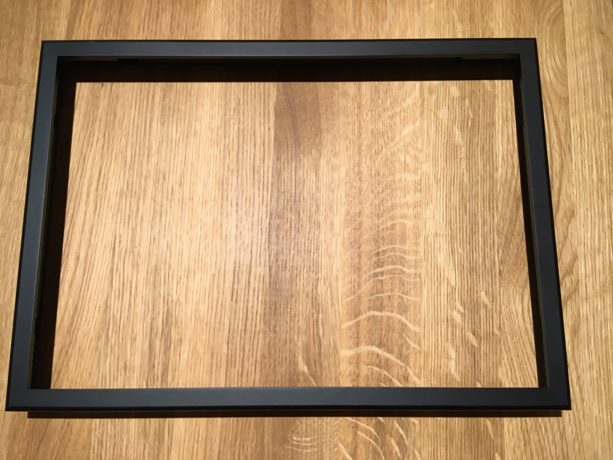 |
| Rear shell | 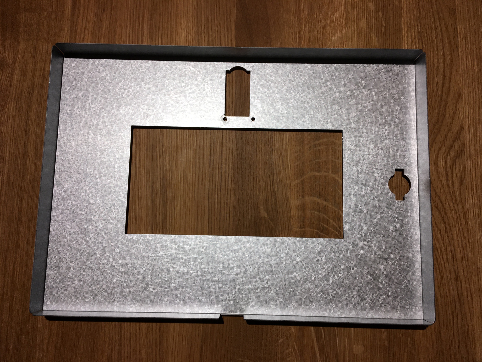 |
| Rear panel |  |
| Momentary switch with status LED | 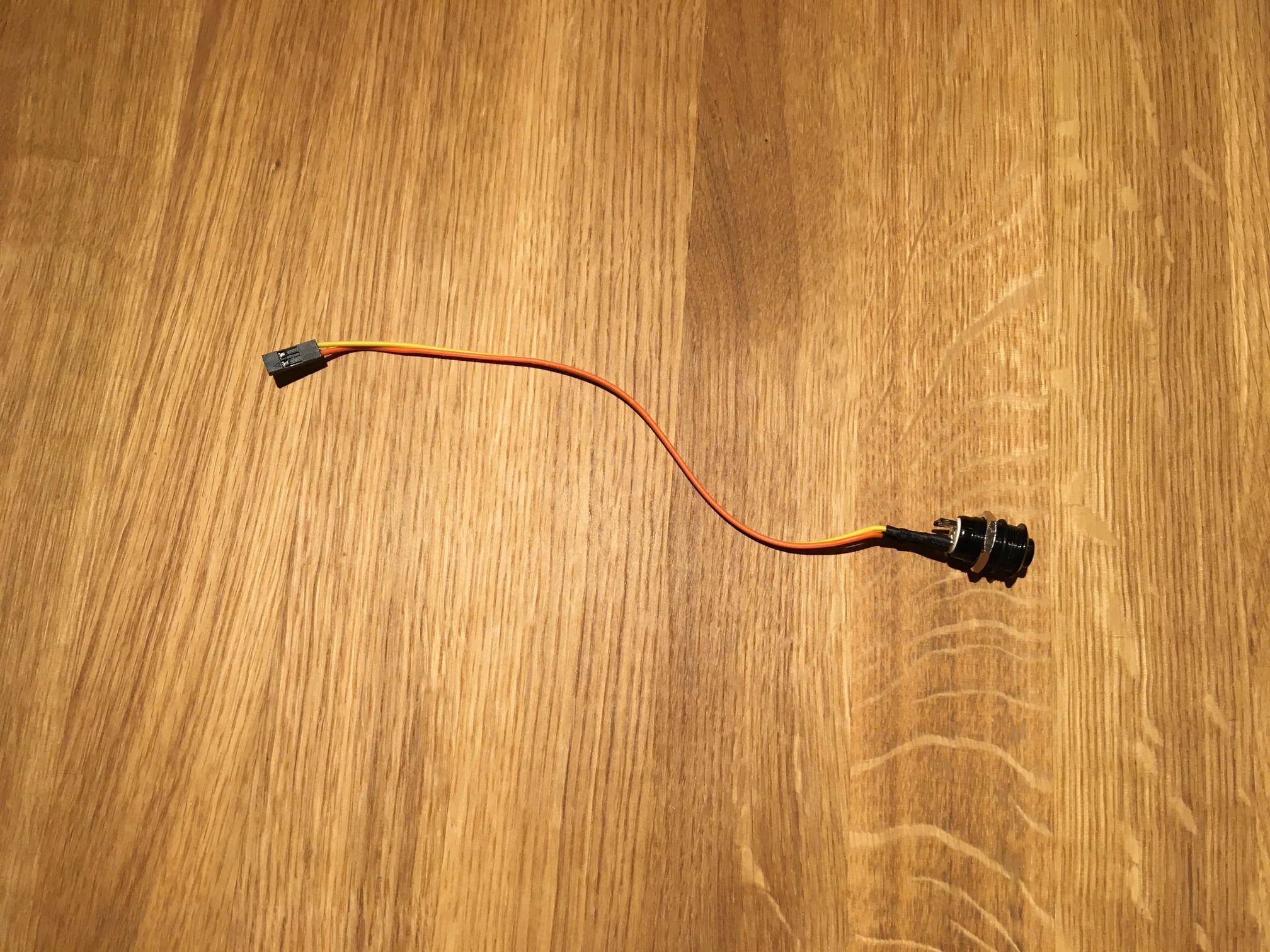 |
| Mainboard | 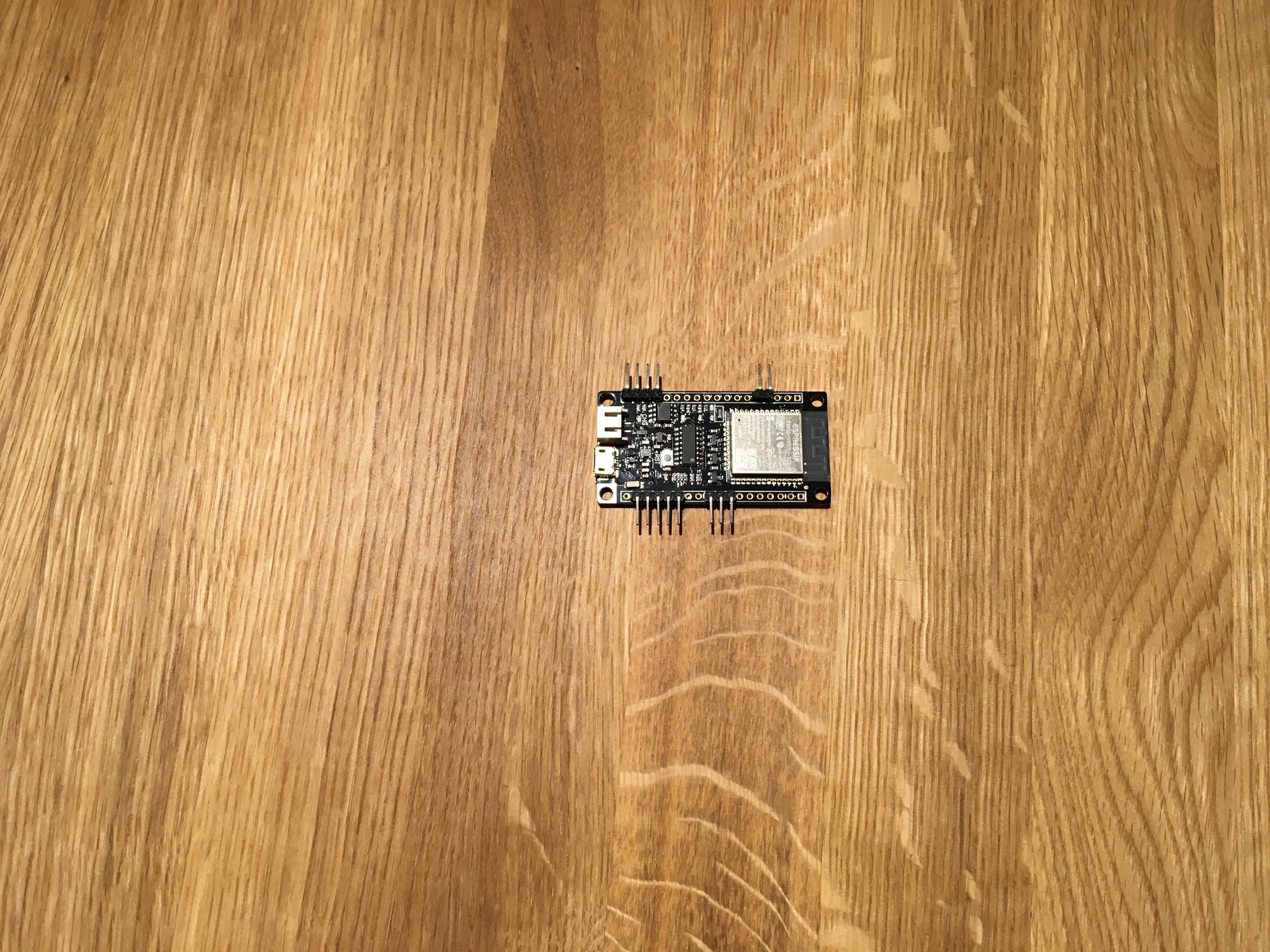 |
| Voltage transformer | 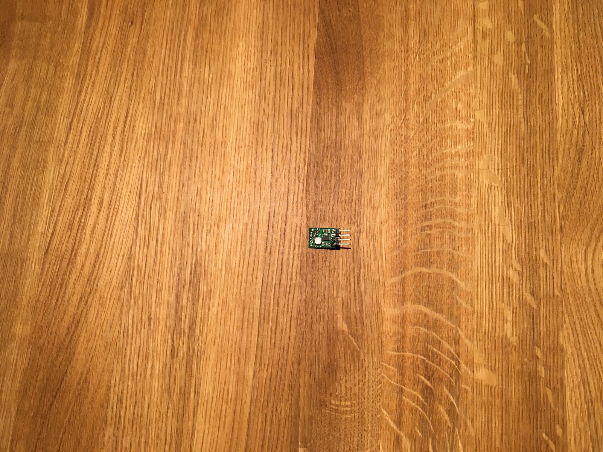 |
| 2x Screws (M3, Hex 2 o. TR8), 2x nuts (M3), 2x spacer (M3) | 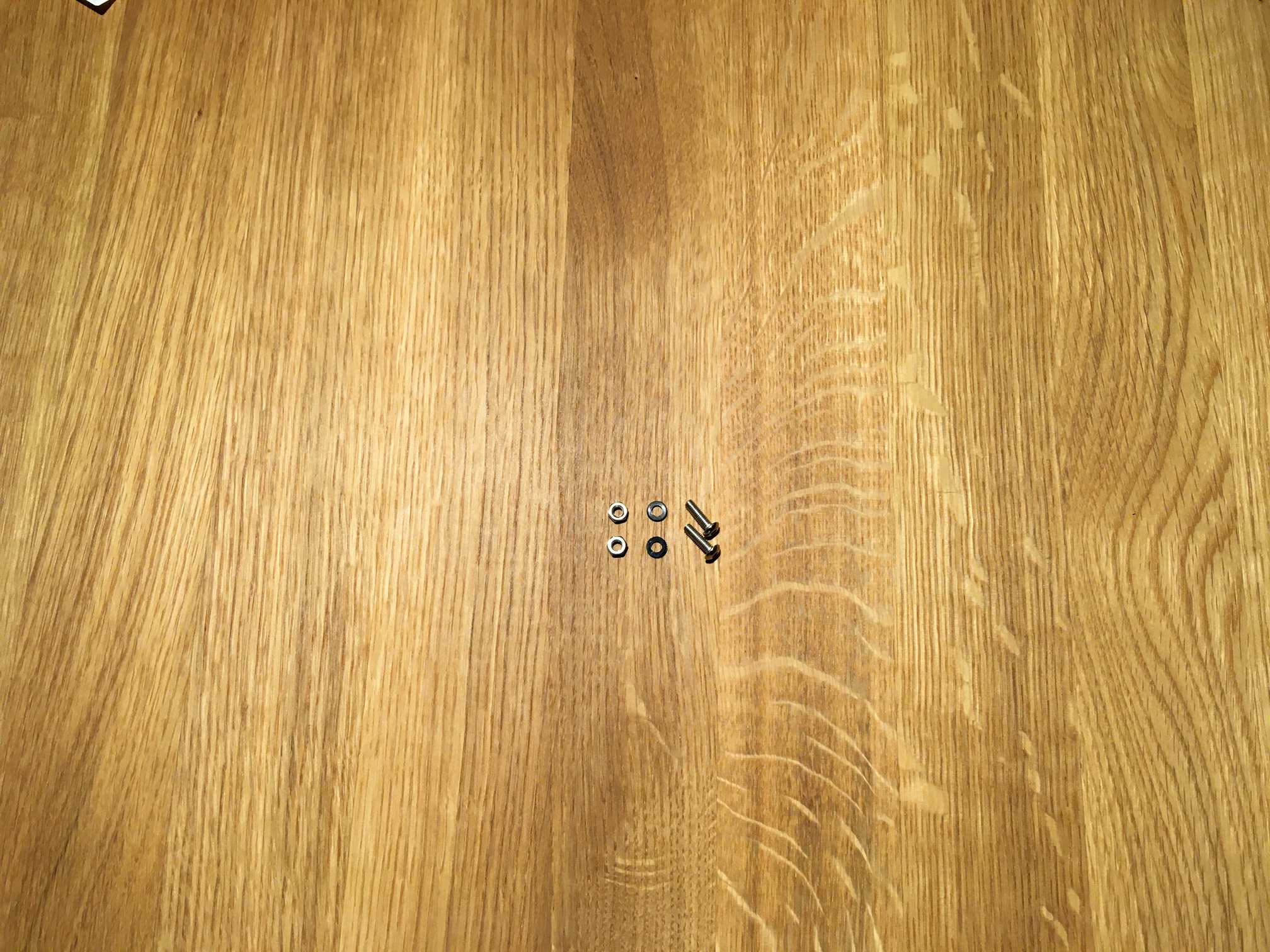 |
| Wire harness | 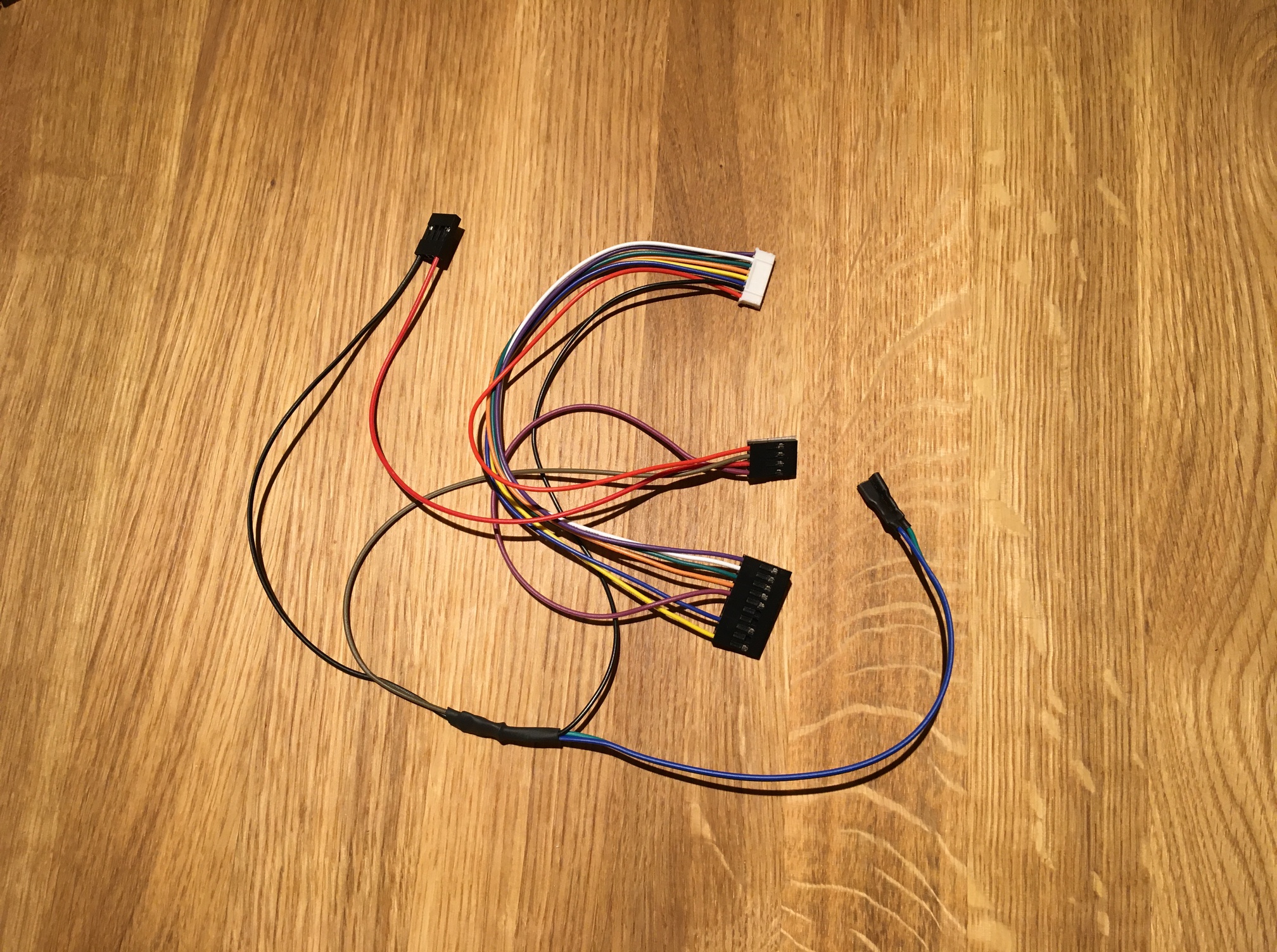 |
| Battery | 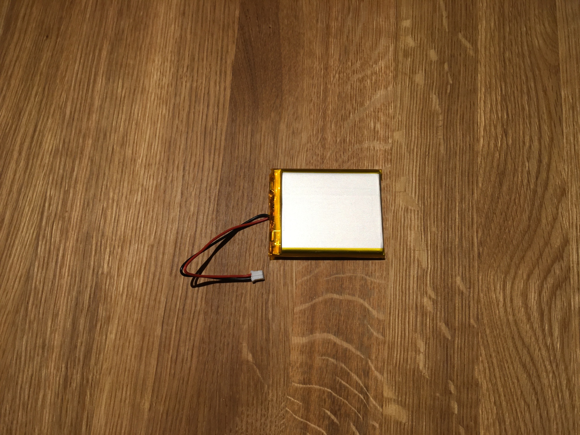 |
| USB to Micro USB cable | 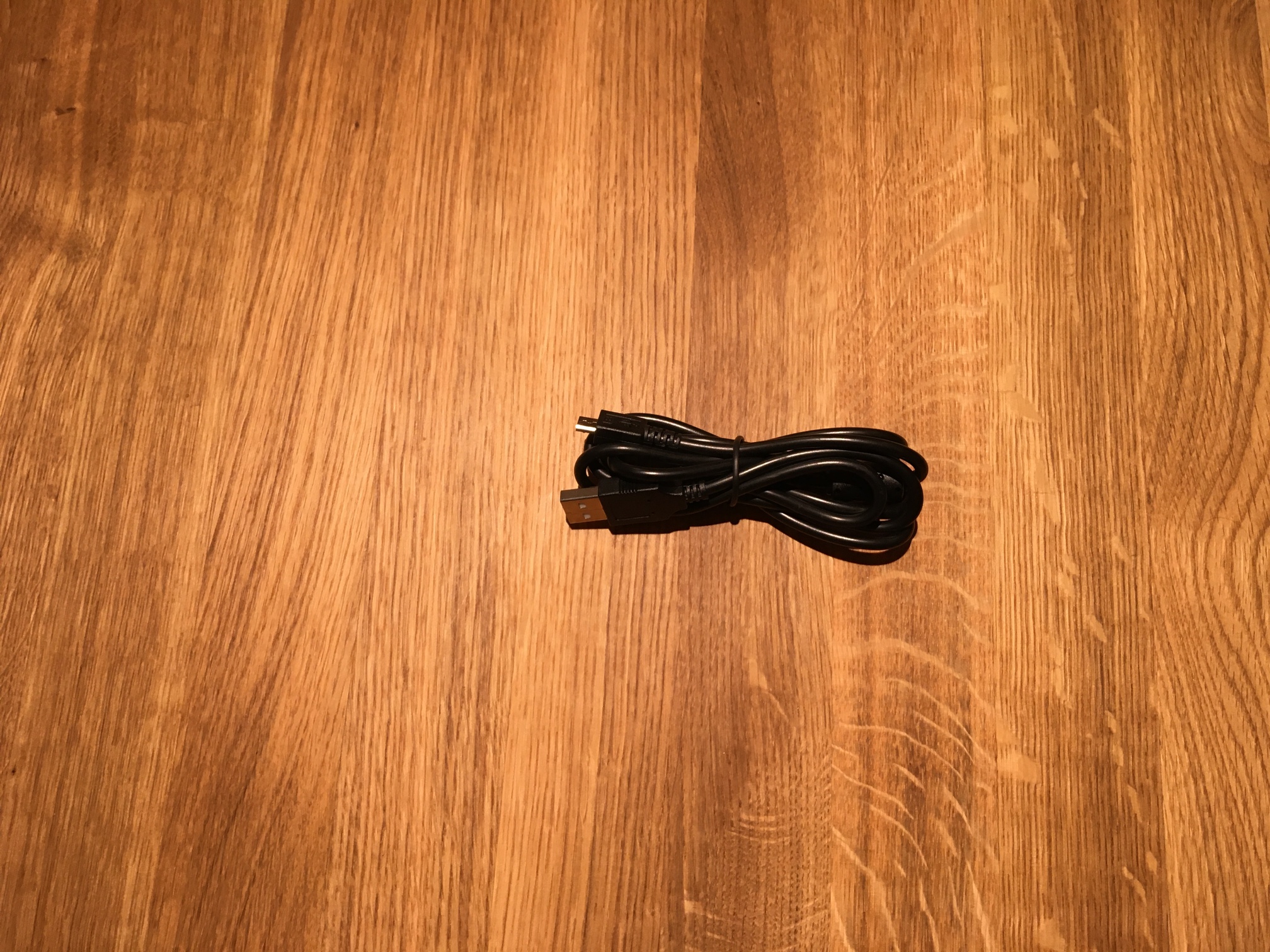 |
Assembly
| ⚠ Caution |
|---|
| Never use force when assembling the device. All components can be connected and disconnected without using force. To disconnect a connection, do not pull directly on the cables. Instead, gently wiggle the connector until it releases from the socket. |
| ⚠ Caution |
|---|
| Be especially careful when handling the display flex cable to avoid damaging it. The flex cable is very fragile and can easily tear, especially when subjected to shear or tensile forces. |
| ⚠ Caution |
|---|
| Make sure that the device is de-energized before disconnecting or connecting any cables. The device must not be connected to a micro USB cable or the battery during this time. |
The assembly of your ArtFrame is done in ten easy steps:
| Assemby step | Image |
|---|---|
| Put the rear panel into the rear shell. | 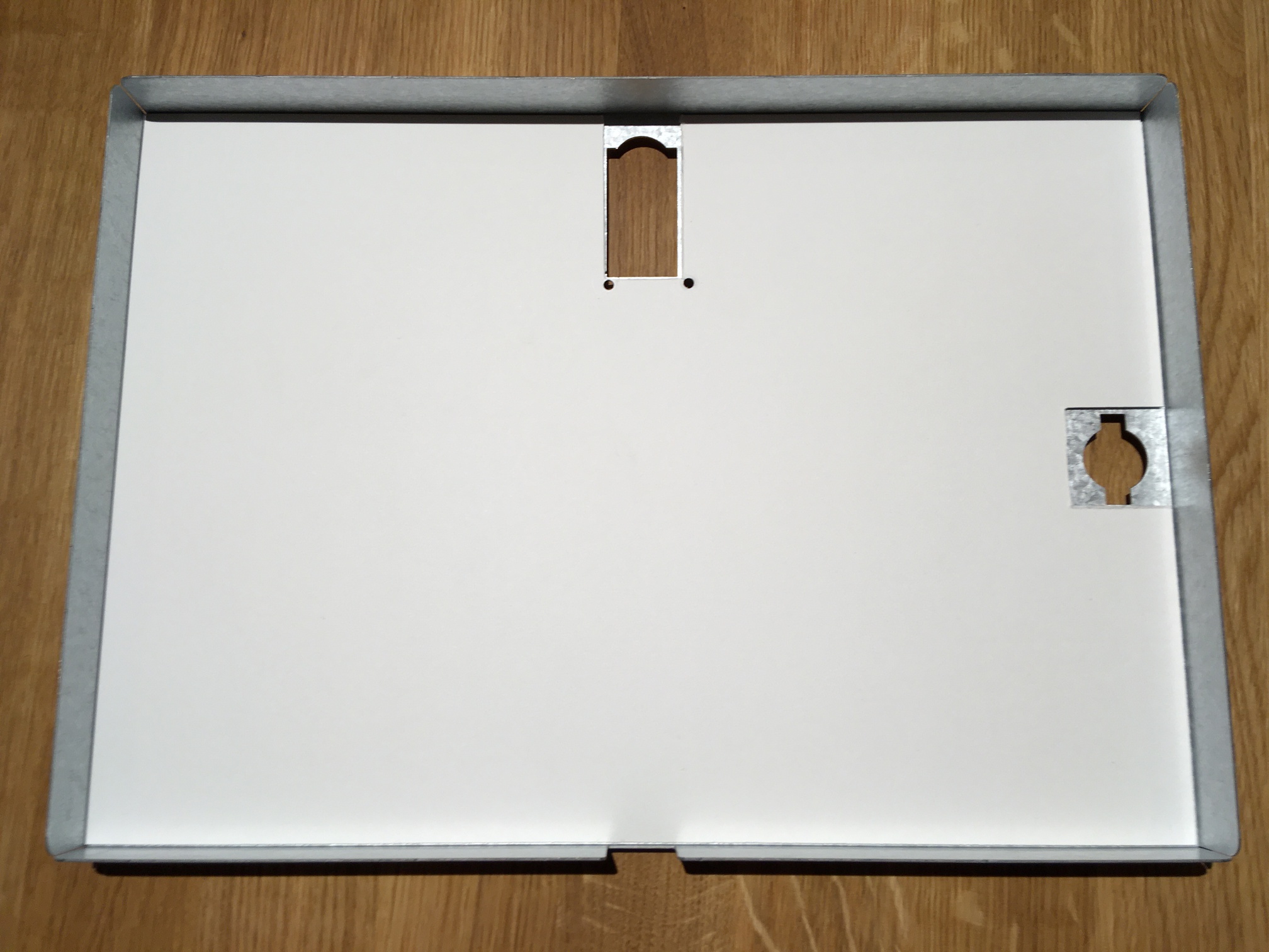 |
| Mount the mainboard with the screws, nuts and spacers to the back plate. The screw heads need to face towards the outside, the nuts face the inside of the back plate. The spacers go between Mainboard and back plate. | 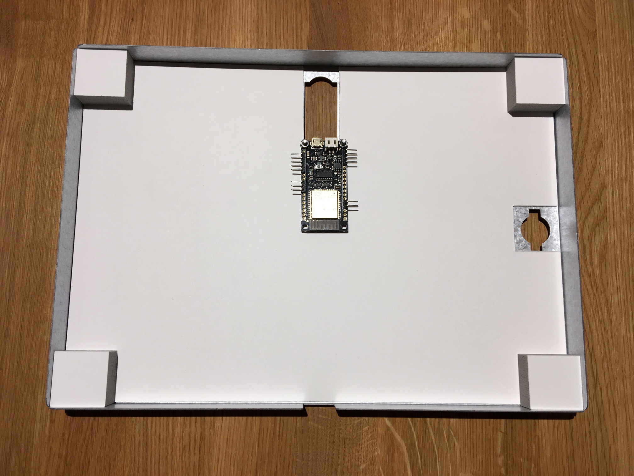 |
| Connect the wire harness. The visible metal contacts of the connectors always face upwards. ⚠ Attach the connectors by applying gentle counter pressure on the pins. Never apply pressure on the mainboard. | 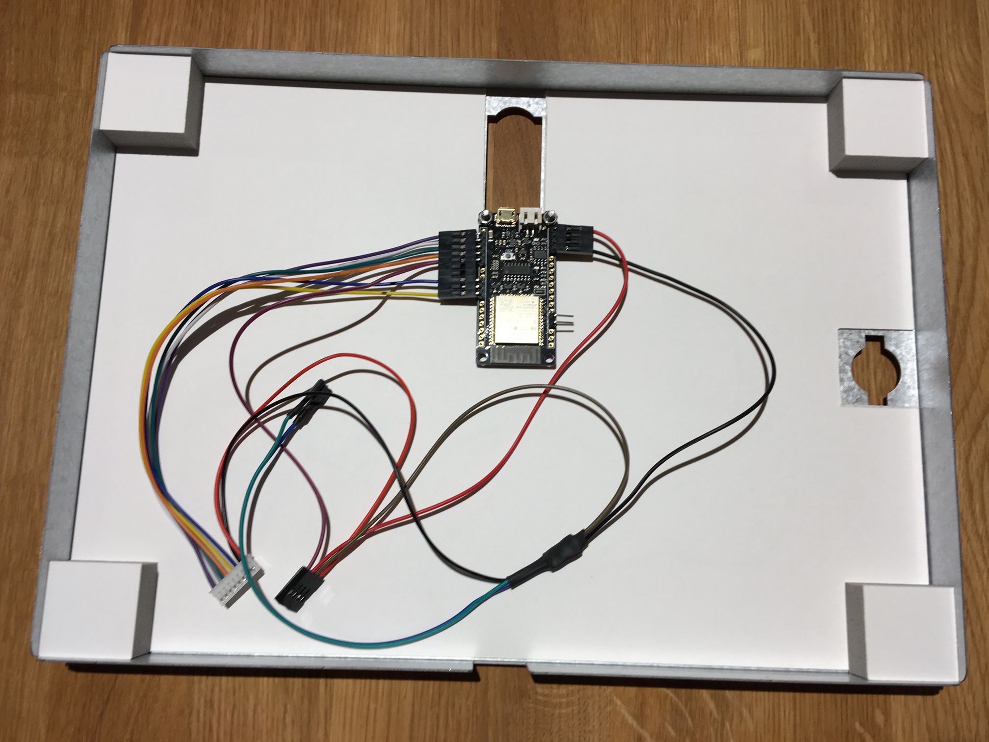 |
| Insert the voltage transformer into the cable harness and glue it into the rear panel. The purple cable must be connected to the SHDN output of the voltage transformer. | 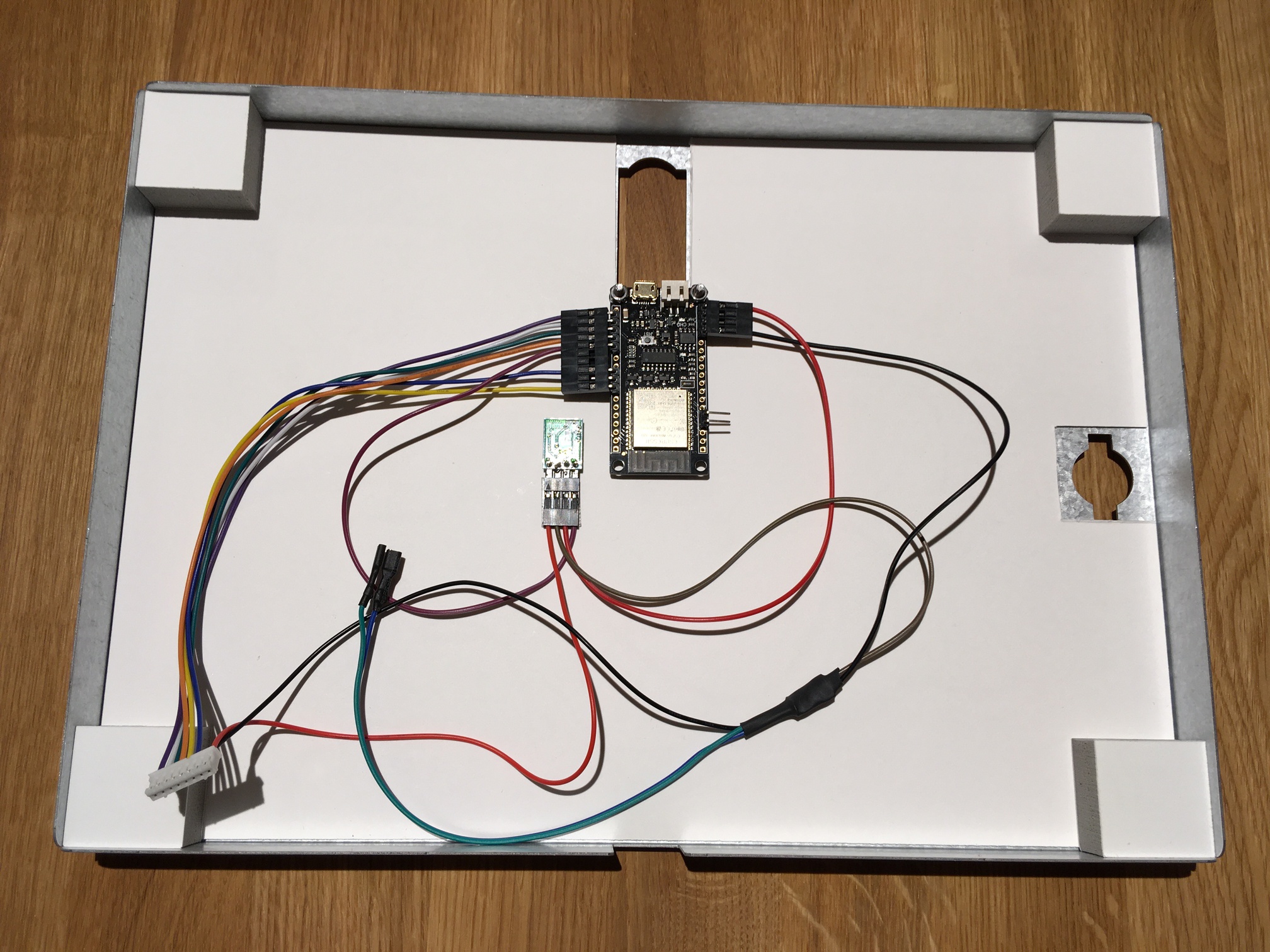 |
| Glue the battery in place, but without connecting it. Then guide the connection cable through the opening in the rear panel. ⚠ Do not connect the battery until the display is connected. | 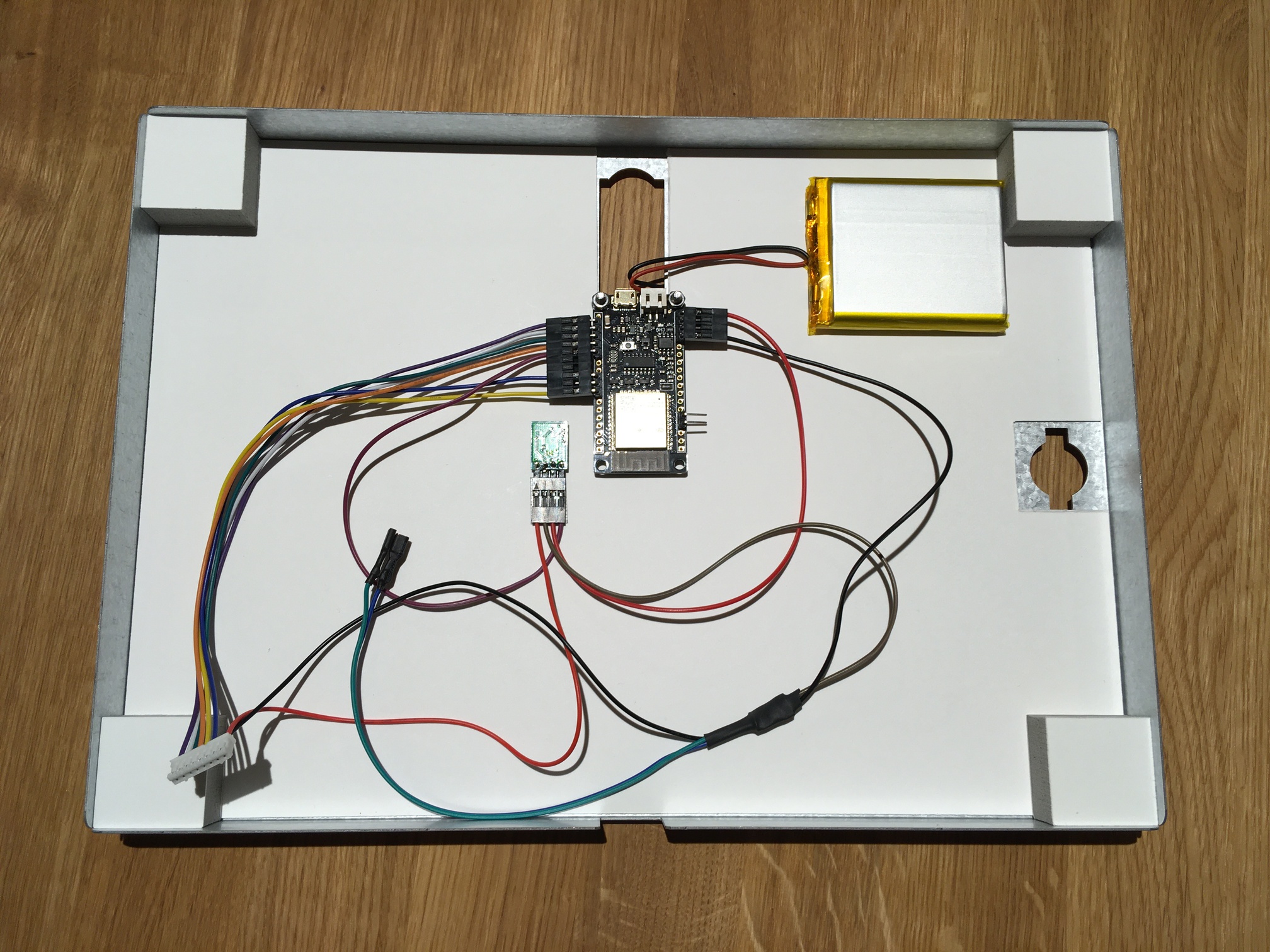 |
| Screw the LED momentary switch into the frame. | 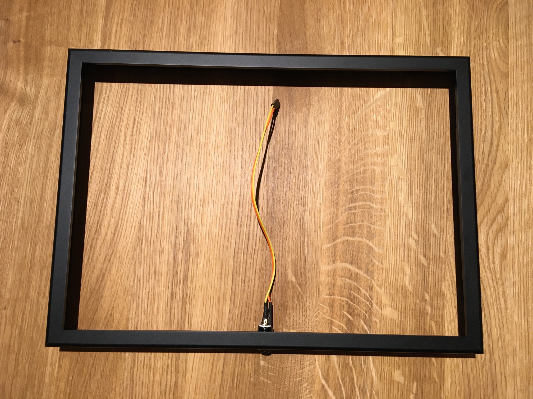 |
| The LED button has four contacts. The orange cable must be connected to the contact with the + symbol, the yellow cable to the left or right of it. The connected green and blue cable is connected to the two remaining contacts in arbitrary order. | 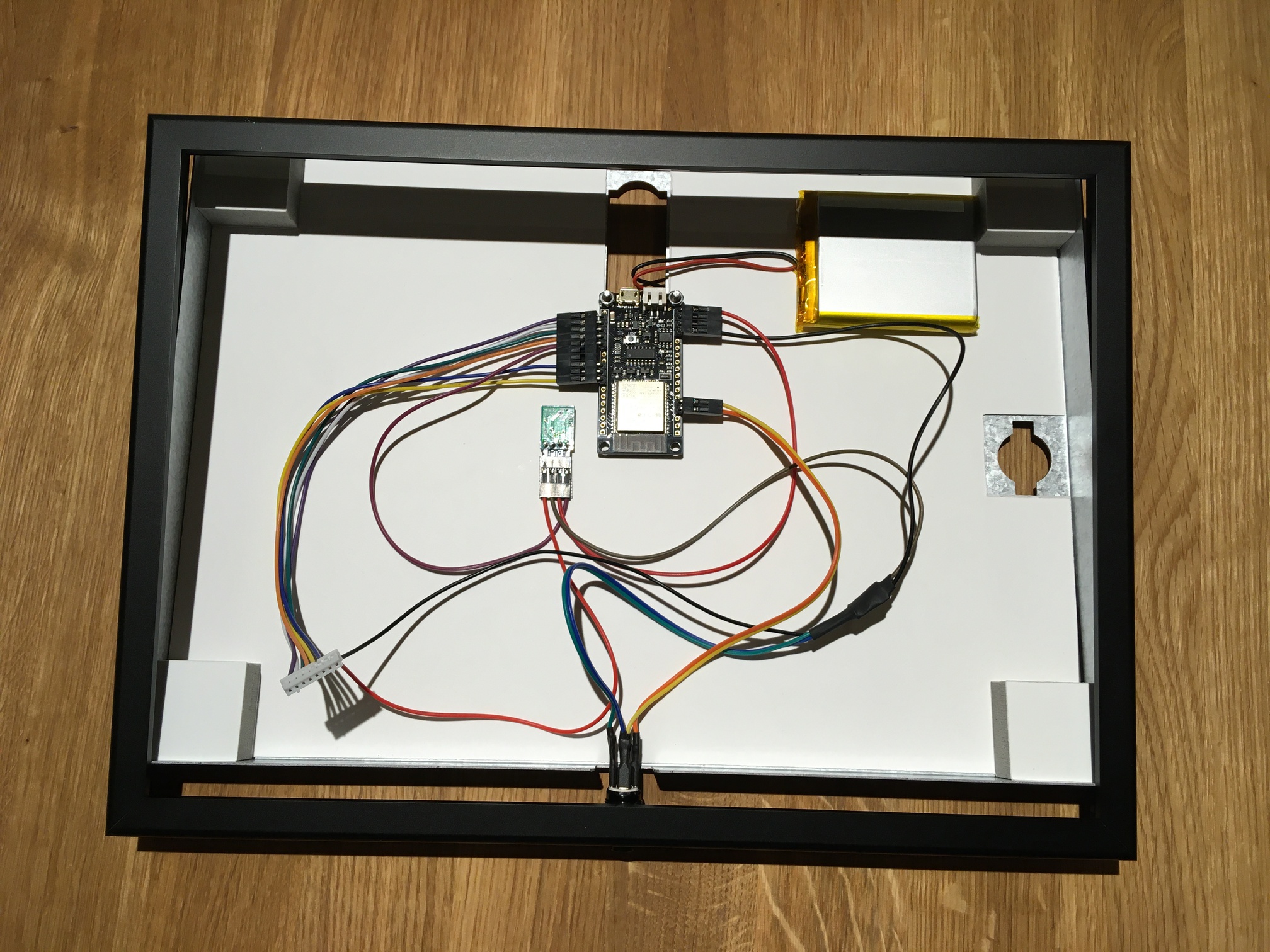 |
| Connect the display driver board to the cable harness (white connector). ⚠ Make sure that there is no tension on the wires at any time. | 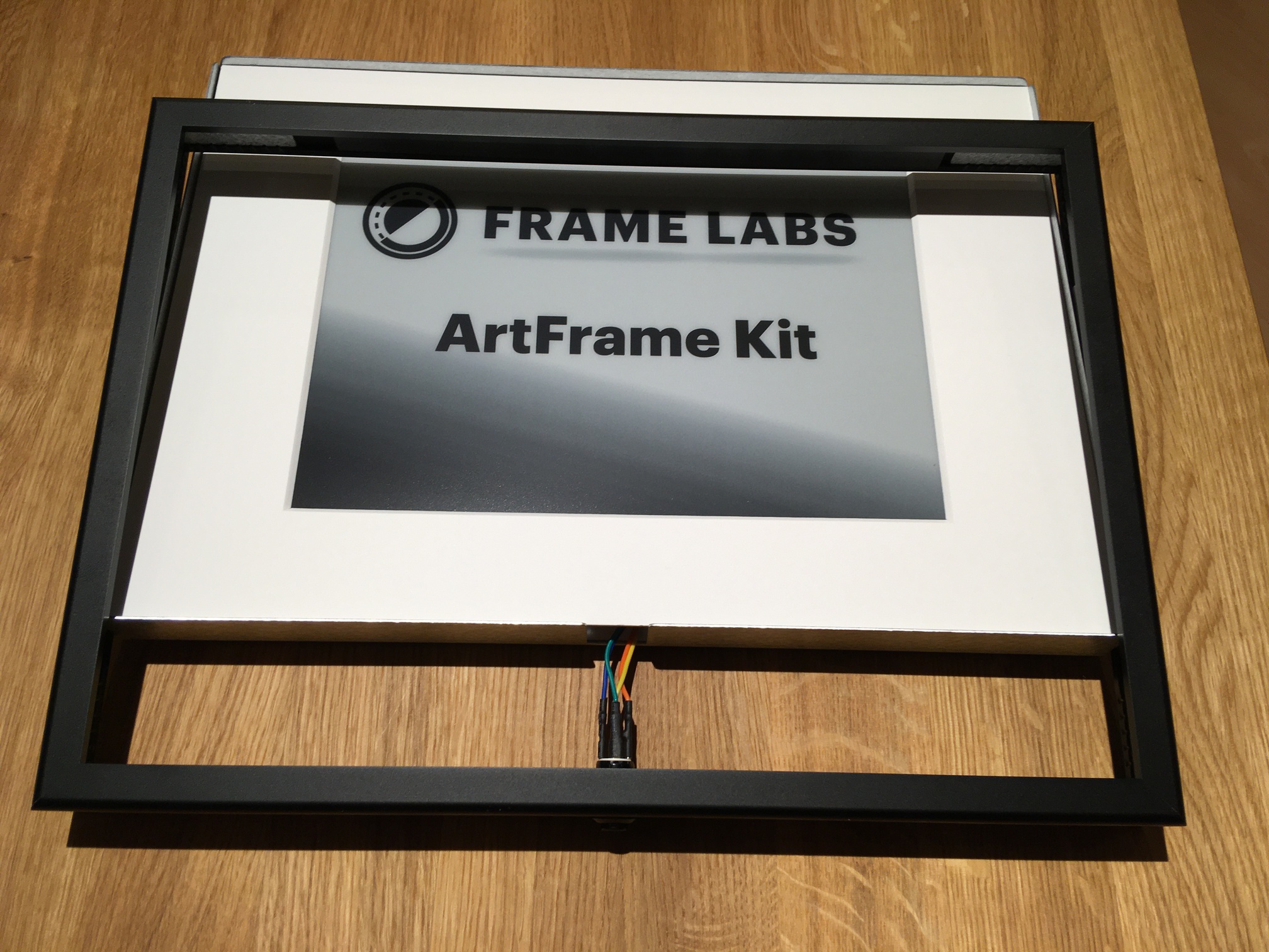 |
| Insert the glass into the rear panel with the matte side facing up. Make sure that there are no dirt particles between the display and the glass. Then slide the frame over the back panel so that the LED button is threaded into the recess and push it in gently. ⚠ Do not try to force the LED button in, otherwise the display's ribbon cable could be damaged. | 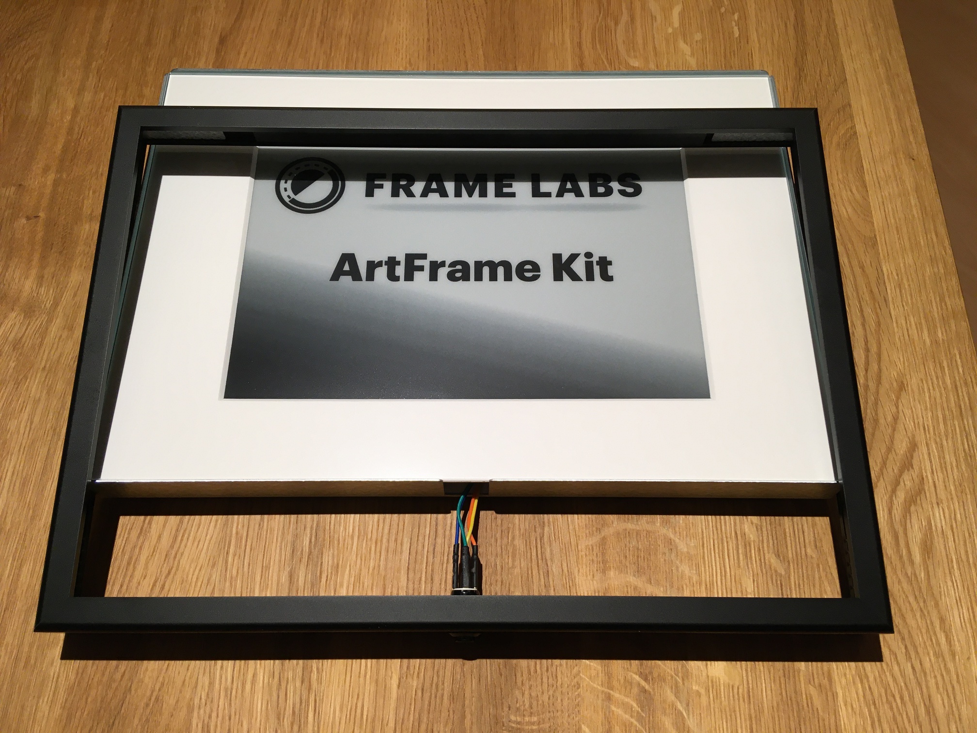 |
| Connect the battery to the motherboard. |  |
To open the device, simply follow the steps backwards.